K51-AVR
2 of 7
EXPERIMENTAL CARD FOR 8051 AND AVR MICROPROCESSORS FAMILY
 Salvatore Damino
|
K51-AVR 2 of 7 EXPERIMENTAL CARD FOR 8051 AND AVR MICROPROCESSORS FAMILY |
|

SECOND PART
In the previous issue (E.F. n° 199
- November 2000) we mounted the K51-AVR card and, as
a final action, we executed the alarm clock program. As You have
seen the program runs autonomously and it requires only a connection
to a power supply source. The alarm clock program drives the on
board buzzer to manage the striking bell and, above all, it has
many comments that clarify the reason why of the performed choices,
even for the unexperienced programmers.
As for all the micro electronics applications the complete knowledge
of the software (or more properly in this conditions: the firmware)
is only one of the presupposed requirements to advantageously
operate in this area. Another aspect, of the same importance,
is the complete knowledge of the used hardware. For these reasons
it is really important to get the data sheets of all the components
installed in the system. Thanks to internet, today is really easy
to find these information from the web network but, for the lazy
people or to simplify the research, we inform You that they are
available in grifo® site.

Real Time Clock - PCF 8583
This integrated circuit has 8 pins
and it is a diffused clock manufactured by Philips that is driven
through the comfortable I2C-BUS.
To connect the component to the others devices that use this protocol,
only 2 interconnection wires are sufficient. The firmware
can properly communicate with all the devices with no requiements
of complicated external addressing circuits.
To correctly operate, the PCF 8583 needs only a 32 KHz
crystal, a battery and few passive components. The diagram
block shows that the component includes also an internal RAM
read and write directly through the same I2C-BUS interface.
These 256 bytes of RAM can mantain the saved information
by taking advantage from the clock battery. In this way the external
CPU can manage different allarm conditions or the activation
of external I/O devices as: the illumination; the garden
irrigation control; the room heating; etc.
A further line managed by PCF 8583 is pin 7 that
is an /INT signal capable to drive an external system,
when a proper internal register is correctly setted. Moreover
this line is connected to a visualization LED that shows
its status.
The current time is displayed through the four digits driven by
SAA 1064, while the four push buttons available on the
card are used to manage the clock setting modalities.

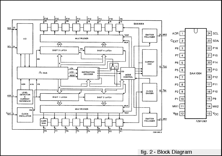
SAA 1064 controller
The controller for 4 digits, 7
segments, LEDs display named SAA 1064 is another
device driven with I2C-BUS protocol. As You can see in
the block diagram, the SAA 1064 includes all the driving
circuit, with constant current generator, for 4 digits
7 segments display and it needs only two external transistors.
By using dedicated I2C-BUS commands it is possible to select
between different brightness levels.

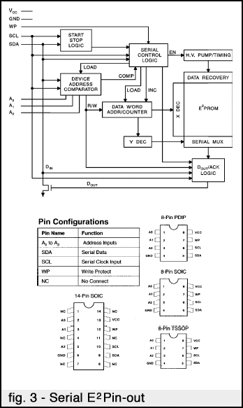
Serial EEPROM
Among the devices managed through I2C-BUS,
independently by the used CPU, the classic serial EEPROM
is certainly needed.
The circuit used in the K51-AVR card is capable to manage
up to 1 Kbyte of serial EEPROM with I2C-BUS modality.
This mean that the device up to 24C08 size can be mounted.
To simplify the understanding of the management tecniques two
separate programs have been developed: one reads the data saved
on EEPROM and the other writes data. The visualization
of the data is performed on the 4 displays of the card
while the commands are entered through the 4 push buttons available
on the board. With these features the programs require only a
power supply voltage.

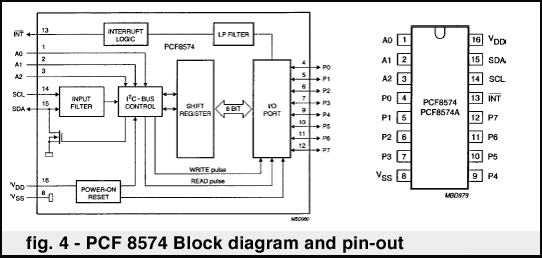
PCF 8574
The PCF 8574 is a device that manages
8 bidirectional I/O lines via I2C-BUS protocol.
The PCF 8574 allows to drive individually the 8 lines available
on this integrated circuit by setting the direction (input or
output) too. Also in this circumstance only the K51-AVR
resources are used both for data visualization and line setting.
To check the I/O lines status can be used the comfortable
TI/O 16 card, a little board self made with 8 LEDs and
8 keys or a normal tester.
By using the provided electric diagram the user can add the suitable
number of PCF 8574, add a buffer circuit for the output
lines and an optocoupled interface for the input lines. The resulting
I/O unit can be connected to external systems without problems,
even if the systems are very complicated.
Data sheets
- Real Time Clock PCF
8583 with lithium battery, RAM and alarm.
- 4 digits, 7 segments, LEDs display controller,
SAA 1064.
- Serial EEPROM, type 24C08.
- 8 bidirectional I/O lines controller, PCF
8574.
Technical documentations available on www.grifo.it
| Articles | | 1 | | 2 | | 3 | | 4 | | 5 | | 6 | | 7 |
Page up-dated at August 29, 2004
GRIFO®
Via dell'Artigiano, 8/6
40016 San Giorgio di Piano
Bologna ITALY
Tel: +39 051 892.052 (4 lines)
FAX: +39 051 893.661
![]() Home
Home ![]() Index
Index ![]() Categorical Index
Categorical Index ![]() CPU
Tables
CPU
Tables![]() The
Demo Programs
The
Demo Programs  Es.
BAS. K51
  Mini Modules